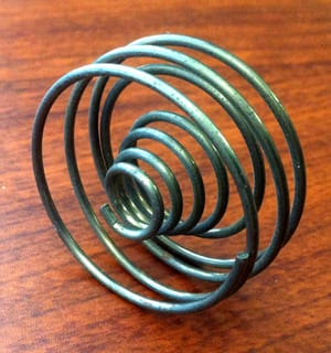
Conical spring compression spring
Conical COMPRESSION SPRINGS are open-coil helical springs wound or constructed to oppose compression along the axis of wind. Helical Compression Springs are the most common metal spring configuration. Generally, these coil springs are either placed over a rod or fitted inside a hole. When you put a load on a compression coil spring, making it shorter, it pushes back against the load and tries to get back to its original length. Compression springs offer resistance to linear compressing forces (push), and are in fact one of the most efficient energy storage devices available.
Configurations: The most common compression spring, the straight metal coil spring, has the same diameter for the entire length. Other configuration options for compression coil springs include hourglass (concave), conical and barrel (convex) types. The straight coil spring configuration is the standard coil type for Stock Compression Springs.
All Katy Spring Stock Compression Stock Springs, Springs, Instrumentation Series Compression Stock Spring .Compression Stock Spring Series, feature squared and ground ends. Ground ends provide flat planes and stability. Squareness influences how the axis force produced by the spring can be transferred to adjacent parts. Although open ends may be suitable in some applications, closed ends afford a greater degree of squareness. Squared and ground end compression stock springs are particularly useful in applications in which 1) high-duty springs are specified, 2) unusually close tolerances on load or rate are needed, 3) solid height must be minimized, 4) accurate seating and uniform bearing pressures are required and 5) a tendency towards buckling must be reduced.
Applications: Compression Metal Springs are found in a wide variety of applications ranging from automotive engines and large stamping presses to major appliances and lawn mowers to medical devices, cell phones, electronics and sensitive instrumentation devices. Cone shape metal springs are generally used in applications requiring low solid height and increased resistance to surging.
Key Parameters:
- Dimensions: Outer Diameter, Inner Diameter, Wire Diameter, Free Length, and Solid Height.
- Free Length is the overall length of a spring in the unloaded position.
- Solid Height is the length of a compression spring under sufficient load to bring all coils into contact with adjacent coils.
- Spring Rate (stiffness)
- Spring Rate is the change in load per unit deflection in pounds per inch (lb. /in.) or Newtons per millimeter (N/mm).
- Unit of Measures
Stress: The dimensions, along with the load and deflection requirements, determine the stresses in the spring. When a compression spring is loaded, the coiled wire is stressed in torsion. The stress is greatest at the surface of the wire; as the spring is deflected, the load varies, causing a range of operating stress. Stress and stress range govern the life of the spring. The higher the stress range, the lower the maximum stress must be to obtain comparable life. Relatively high stresses may be used when the stress range is low or if the spring is subjected to static loads only. The stress at solid height must be high enough to permit presetting, yet low enough to avoid permanent damage since springs are often compressed solid during installation.
Ordering Conical Compression Springs
The basic information needed by Katy Spring in order to assist our customers with compression springs is material, wire size, free length, number of coils, travel, diameter, end types, finish, works over, works in, and maximum solid height. Katy Spring can assist our customers in determining design parameters for compression springs if only partial data is available.
Music wire, hard-drawn MB, oil-tempered MB, and stainless steels are the most popular materials. Alloy steels such as chromium-silicon and chromium-vanadium are often used. Copper-based alloys such as beryllium-copper, phosphor-bronze, and spring brass are occasionally required, as are the proprietary nickel-based alloys such as Inconel, Monel, Ni-Span C, Elgiloy and so on.
Determining wire size is part of the design method process for compression springs. The methods used for design evolved from trail-and-error method observations all the way up to today’s modern methods of spring design software which is incorporated by Katy Spring to assist our customers with wire size selection.
The least expensive and most used type of end, where the index D/d is above 10, is with closed ends, not ground; this type is especially satisfactory for light wire sizes less than .031 in. in diameter. The second most useful type, especially where small load tolerances or minimum buckling is required, is the “squared and ground”; this type also provides more uniform loading and will stand upright without tipping. The open ends and the open ends ground are seldom used, as they often tangle together during shipping; they cannot sand upright and do not exert uniform loads.
The outside diameter of a compression springs increases when deflection occurs. This change is because the slope or angle of the coils relative to the axis of the spring changes when deflection takes place. Allowance for this change should be made when a compression spring is housed in a tube to prevent friction or binding which can cause increased stresses and subsequent early failure.
Compression springs subjected to the dynamic effects of vibration, natural frequency, and surge and rapid force oscillations may have stresses increased as much as 40 percent or more. This is due to the inertia effect of the coils because suddenly applied forces make the first, second and third coils deflect more than other coils, and this explains why many springs break on one of these three coils. Most fractures occur on the third coil due to coil clashing.
Reduction of surge and resonance with harmonics in compression springs is usually accomplished by coiling one or two active coils near one end at a reduced pitch. These coils then close up and come together, thereby changing the natural frequency of the spring. Other methods to reduce surging include using two springs, one within the other, stiffening the spring to increase the force, or by using square or rectangular wire.
Buckling of helical compression springs often occurs when the free length is four times more times the mean diameter. The amount of deflection and the slenderness ratio are the dominating factors. The type ends is important, and for most applications where buckling occurs, it is highly desirable to have the ends closed and ground. Such springs should be guided over a rod or in a tube to retard buckling, and the rods or tubes should be lubricated to reduce friction.
Here is a list of notes in addition to the above to keep in mind when ordering compression springs from Katy Spring:
- The normal square ness tolerance for ground ends is 2-3 degrees.
- Use conical compression springs when a short, solid height is needed to reduce buckling and surging.
- Leave the wind direction optional for compression springs. Use right hand wound when the compression spring is being threaded on a bolt, one right and one left when two springs are being used inside the other to avoid meshing coils.
- Specify a force with a tolerance (+/- 10 percent) at an exact compressed height rather than a definite deflection. Spring rate is the difference of two forces divided by the amount of deflection between those forces.
- Make Katy Spring aware of unusual conditions such as temperature, corrosive environments, impact force, and fatigue life.
- Specify the mandatory requirements only to Katy Spring. Leave the exact wire size and number of coils to the discretion of Katy Spring whenever possible.
- Make Katy Spring aware of the spring travel and any solid height requirements.
- After the parameters are determined, view Katy Spring’s online catalog for a possible match to your compression spring need.